|
Cable Pin-outs
 PDF format of Cable pin-outs PDF format of Cable pin-outs
-click on cable or connector name for pin-outs-
RS-422 Serial Device Control cable
Echo Plug for serial port testing
Serial Printer cable for VPE Series
Serial Printer cable for DPE Series
CGA Monitor cable (SBC1,2,3)
VGA Monitor cable(SBC 4)
9pin to 15 pin CGA
adapter
Analog RGB cable for
Sony PVM-1390
Ten XL Switch Settings
Performer Switch Settings
Ten XL Preview Preselector cable
Performer Preview Switcher cable
Performer Preview Preselector cable
Dubner 5/10/20k Character Generator cable
Dubner CBG/Texta Character Generator cable
Dubner 30k/Graphics Factory/Presto Character
Generator cable
Dubner/Digital Graphics/Pinnacle
TypeDeko Character Generator cable
TypeDeko cable using
B&B 422CON converter
Alternate TypeDeko cable (PC COM Port
/ RS-232 mode)
DPE-500 Series GPI connector pin-outs
VPE-300 Series GPI connector pin-outs
VPE-151 GPI connections (37 pin)
VPE-141/241 (24 pin) GPI connector
pin-outs
8451 GPI connections
8465 Preview
Switcher (9pin to mini-XLR)
8465 Preview
Switcher Parallel port
K5 Keyboard cable (25pin)
K5 Keyboard interconnect
cable (9pin)
K5 keyboard cable
schematic
K2 Keyboard extension (also K3 cable)
Profile PDR-200 LTC connector (4 in /
4 out)
Yamaha 03D/02R to Fastrack interconnect
cable (DB-9 to PS-2/mini-Din)
Evertz HD9625DSK cable for Fastrack GPI
control
Back
to Support
RS-422 Serial Device control cable
Editor
(9 pin-Male) |
SIGNAL
(twisted pairs) |
Serial Device
(9 pin-Male) |
1
9 |
Chassis Ground* |
1
9 |
2
7 |
RxA
RxB |
2
7 |
3
8 |
TxB
TxA |
3
8 |
4
6 |
Signal Ground |
4
6 |
*Note: Chassis
Ground wires should be grounded to the cable connector housing
and connector screwed into frame for proper grounding.
Back to TOP
ECHO PLUG
for Serial Port testing
|
SIGNAL |
|
2 |
Rx- to TX- |
8 |
|
3 |
RX+ to TX+ |
7 |
 Back to TOP
Serial Printer cable (VPE Series)
|
Editor (9 pin) |
SIGNAL |
Printer (25 pin) |
|
1 |
Chassis Ground* |
1 |
|
2 |
RS-232 Rx |
2 |
|
4 |
Signal Ground |
7 |
|
6 |
Signal Ground |
7 |
|
8 |
RS-232 Tx |
3 |
|
9 |
Chassis Ground |
1 |
Note: Editor
Printer port set for RS-232 protocol at 1200 baud, 8 data bits,
1 stop bit and no parity. Printer is set up for XON/XOFF protocol.
*Chassis Ground wires should be grounded to the cable connector
housing and connector screwed into frame for proper grounding.
Back to TOP
Serial Printer cable (DPE Series)
|
Editor (9 pin) |
SIGNAL |
Printer (25 pin) |
|
1 |
Chassis Ground* |
1 |
|
2 |
RS-232 Rx |
2 |
|
4 |
Signal Ground |
7 |
|
6 |
Signal Ground |
7 |
|
3 |
RS-232 Tx |
3 |
|
9 |
Chassis Ground |
1 |
Note: Editor
Printer port set for RS-232 protocol at 1200 baud, 8 data bits,
1 stop bit and no parity. Printer is set up for XON/XOFF protocol.
*Chassis Ground wires should be grounded to the cable connector
housing and connector screwed into frame for proper grounding.
Back to TOP
CGA Monitor cable
(SBC-1/2/3)
|
Editor (9 pin) |
SIGNAL |
CGA (9 pin) |
|
1 |
Red/Blue Ground |
1 |
|
3 |
Red |
3 |
|
2 |
Green Ground |
2 |
|
4 |
Green |
4 |
|
5 |
Blue |
5 |
|
6 |
Horizontal Ground |
6 |
|
8 |
Horizontal Sync |
8 |
|
7 |
Vertical Ground |
7 |
|
9 |
Vertical Sync |
9 |
Back to TOP
VGA Monitor cable
(SBC-4)
|
Editor (9 pin) |
SIGNAL |
VGA (15 pin) |
|
1 |
Red |
1 |
|
6 |
Red Ground |
6 |
|
2 |
Green |
2 |
|
7 |
Green Ground |
7 |
|
3 |
Blue |
3 |
|
8 |
Blue Ground |
8 |
|
4 |
Horizontal Sync |
13 |
|
5 |
Vertical Sync |
14 |
Back to TOP
9-pin to 15-pin adaptor
|
9 pin (male) |
15 pin (female) |
|
1 |
1 |
|
2 |
2 |
|
3 |
3 |
|
not used |
4 |
|
not used |
5 |
|
6 |
6 |
|
7 |
7 |
|
8 |
8 |
|
not used |
9 |
|
9 |
10 |
|
9 |
11 |
|
not used |
12 |
|
4 |
13 |
|
5 |
14 |
|
not used |
15 |
Back to TOP
Custom Analog RGB Cable for Sony PVM-1390 Monitor
|
25 pin (female) |
9 pin (male) |
|
2 |
6 |
|
4 |
3 |
|
5 |
2 |
|
6 |
1 |
|
2 to 15 (jumper) |
-- |
Analog RGB with Sync on Green (editor set-up)
Back to TOP
TenXL Switch Settings
(dip switches located on the Serival Interface Adaptor card;
upper left card)
S1
|
1 |
2 |
3 |
4 |
5 |
6 |
7 |
8 |
|
O |
O |
O |
O |
O |
O |
O |
C |
C = Closed, O = Open
S2
|
1 |
2 |
3 |
4 |
5 |
6 |
7 |
8 |
|
C |
C |
C |
C |
C |
C |
C |
C |
Back to TOP
Ten XL Preselector & Performer Preview Switcher/Preselector
cable
|
Editor (9 pin, Male) |
SIGNAL |
Switcher (25 pin, Male) |
|
2 |
RxA |
2 |
|
7 |
RxB |
1 |
|
1 |
Chassis Ground* |
18 |
|
8 |
TxA |
15 |
|
3 |
TxB |
14 |
*Note:
Chassis Ground wires should be grounded to the cable connector
housing and connector screwed into frame for proper grounding.
Back to TOP
Performer Switch Settings
(More
on Performer switch settings, including photo)
S1
|
1 |
2 |
3 |
4 |
5 |
6 |
7 |
8 |
|
O |
O |
O |
O |
O |
O |
O |
O |
C = Closed, O = Open
S2
|
1 |
2 |
3 |
4 |
5 |
6 |
7 |
8 |
|
O |
O |
O |
O |
O |
C |
X |
X |
X = Verify (suggest Open)
S3 (38.4K Baud)
|
1 |
2 |
3 |
4 |
5 |
6 |
7 |
8 |
|
O |
C |
C |
C |
C |
O |
O |
O |
--- alternatively ---
S3 (9600 Baud)
|
1 |
2 |
3 |
4 |
5 |
6 |
7 |
8 |
|
O |
C |
O |
C |
C |
O |
O |
O |
Back to TOP
Dubner 5/10/20k Character Generator cable
|
Editor (9 pin) |
CG (9 pin) |
|
1* |
2* |
|
2 |
7 |
|
3 |
9 |
|
7 |
6 |
|
8 |
8 |
*Note: Chassis
Ground wires (1-2) should be grounded to the cable connector
housing and connector screwed into frame for proper grounding.
Back to TOP
Dubner CBG/Texta Character Generator cable
|
Editor (9 pin) |
CG (9 pin) |
|
1* |
1* |
|
2 |
8 |
|
3 |
6 |
|
7 |
9 |
|
8 |
5 |
*Note: Chassis
Ground wires should be grounded to the cable connector housing
and connector screwed into frame for proper grounding.
Back to TOP
Dubner 30k/Graphics Factory/Presto Character
Generator cable
|
Editor (9 pin) |
SIGNAL |
CG (9 pin) |
|
1 |
Chassis Ground |
1 |
|
2 |
Rx+ |
8 |
|
3 |
Tx - |
7 |
|
4 |
Signal Ground |
4 |
|
6 |
Signal Ground |
6 |
|
7 |
Rx - |
3 |
|
8 |
Tx + |
2 |
|
9 |
Chassis Ground |
9 |
Note: Chassis Ground
wires should be grounded to the cable connector housing and connector
screwed into frame for proper grounding.
Use Port 12 on the VPE-151; CG port on the VPE-131, 141, 141L,
241, 241L, & 251; and port CHAR GEN on VPE-331, 341, 351.
Back to TOP
Dubner/Digital Graphics/Pinnacle TypeDeko Character
Generator cable
|
Editor (9 pin) |
SIGNAL |
CG (25 pin) |
|
2 |
Tx- |
2 |
|
3 |
Rx+ |
17 |
|
4 |
Chassis Ground* |
7 |
|
7 |
Tx+ |
14 |
|
8 |
Rx- |
5 |
Note1: Set the
TypeDeko COM port to 9600 baud, 8 bits, NO parity, I stop; Flow
Control to NONE.
To connect the TypeDeko’s PC’s COM port (RS232) to
a Grass Valley Editor or Switcher (RS422), you will need a B&B
converter, model 422CON, with plug-in power supply.
* Chassis Ground wires should be grounded to the cable
connector housing and connector screwed into frame for proper
grounding.
Back to TOP
Alternate TypeDeko cable
PC COM Port (RS-232 mode)
Some Grass Valley Switchers may be configured
to use the same 9-Pin port for RS-232. If yours can be so configured,
and you wish to operate this way, the cable is much simpler.
Please consult your switcher manual for the correct jumper settings.
|
TypeDeko (9 pin) |
SIGNAL |
GV Switcher (9 pin) |
|
2 |
Rx |
2 |
|
3 |
Tx |
8 |
|
5 |
Gnd |
4 |
Back to
TOP
Cable connecting TypeDeko to B&B 422CON converter
box
To connect TypeDeko's PC COM port to the VPE requires
adapting the VPE's RS-422 signal to the TypeDeko's RS-232 signal.
TypeDeko PC Com port
DB-9 female |
SIGNAL |
B&B Converter
RS-232 side, DB-25 female |
|
2 |
Rx |
3 |
|
3 |
Tx |
2 |
|
5 |
Gnd |
7 |
Cable connecting VPE to B&B 422CON converter box
B&B RS-422 side
DB-25 male |
SIGNAL |
VPE
RS-422 port, DB-9 male |
|
2 |
Tx |
2 |
|
14 |
Tx+ |
7 |
|
5 |
Rx |
8 |
|
17 |
Rx+ |
3 |
|
7 |
Gnd |
4 |
Back to TOP
K5 Keyboard cable (25pin-25pin)
The K5 keyboard cable (25pin-25pin) connects
between the K5 keyboard and the expansion chassis. The cable
consists of 7 twisted pairs.
|
Editor (25 pin) |
SIGNAL |
K5 (25 pin) |
|
1 |
Chassis Ground |
1 |
2
14 |
Kbd Tx
(twisted pair) |
2
14 |
3
16 |
Kbd Rx
(twisted pair) |
3
16 |
5
17 |
Dsk Tx
(twisted pair) |
5
17 |
6
19 |
Dsk Rx
(twisted pair) |
6
19 |
7
20 |
Ground
(twisted pair) |
7
20 |
8
21 |
Jog Tx
(twisted pair) |
8
21 |
9
22 |
Jog Rx
(twisted pair) |
9
22 |
|
25 |
Chassis Ground |
25 |
Back to TOP
K5 Keyboard interconnect cable (Expansion chassis,
9pin-9pin)
This interconnect cable connects from
the Editor KEYBOARD port to the Expansion chassis KYBD OUT.
Editor
(9 pin-Male) |
SIGNAL
(twisted pairs) |
Serial Device
(9 pin-Male) |
1
9 |
Chassis Ground* |
1
9 |
2
7 |
RxA
RxB |
2
7 |
3
8 |
TxB
TxA |
3
8 |
4
6 |
Signal Ground |
4
6 |
*Note: Chassis
Ground wires should be grounded to the cable connector housing
and connector screwed into frame for proper grounding.
Back to TOP
K2 Keyboard Extension cable (K3 keyboard cable,
9pin-9pin)
This cable extends the K2 and K3 keyboards
longer distances from the Editor.
Editor
(9 pin-Male) |
SIGNAL
(twisted pairs grouped) |
Serial Device
(9 pin-Female) |
|
1 |
Drain |
1 |
2
7 |
RxA
RxB |
2
7 |
3
8 |
TxB
TxA |
3
8 |
|
4 |
Power Ground |
4 |
|
5 |
+12V |
5 |
|
6 |
Ground |
6 |
|
9 |
Chassis Ground |
9 |
Back to TOP
VPE-151 (37pin) GPI connector pin-outs
A 37pin D connector (male) is needed to
plug into the GPI (J24) port on the VPE-151.
Pin numbering starts at upper right as you view the VPE-151 connector,
pins 36-37 are not used.
|
GPI# |
1 |
2 |
3 |
4 |
5 |
6 |
7 |
8 |
9 |
10 |
11 |
12 |
13 |
14 |
15 |
16 |
|
"Hot" |
1 |
2 |
3 |
4 |
5 |
6 |
7 |
8 |
9 |
10 |
11 |
12 |
13 |
14 |
15 |
16 |
|
Common |
20 |
21 |
22 |
23 |
24 |
25 |
26 |
27 |
28 |
29 |
30 |
31 |
32 |
33 |
34 |
35 |
Back to TOP
VPE-141/241 (24 pin block) GPI connector
pin-outs
A 24 pin block connector is needed to
plug into the GPI "port" on the VPE-141/241.
GPI connector block (green) pin numbering (left to right)
|
Pin |
1 |
2 |
3 |
4 |
5 |
6 |
7 |
8 |
9 |
10 |
11 |
12 |
|
Pin 1 |
Chassis Ground |
|
Pin 2 |
Chassis Ground |
|
Pin 3 |
GPI Relay 1 |
|
Pin 4 |
GPI Relay Common |
|
Pin 5 |
GPI Relay 2 |
|
Pin 6 |
GPI Relay Common |
|
Pin 7 |
GPI Relay 3 |
|
Pin 8 |
GPI Relay Common |
|
Pin 9 |
GPI Relay 4 |
|
Pin 10 |
GPI Relay Common |
|
Pin 11 |
Chassis Ground |
|
Pin 12 |
Chassis Ground |
Back to TOP
DPE-500 Series GPI connector pin-outs
A 16 pin connector on the lower right
rear chassis.
|
GPI 8 |
GPI 7 |
GPI 6 |
GPI 5 |
GPI 4 |
GPI 3 |
GPI 2 |
GPI 1 |
|
16 |
15 |
14 |
13 |
12 |
11 |
10 |
9 |
8 |
7 |
6 |
5 |
4 |
3 |
2 |
1 |
Back to TOP
VPE-300 Series GPI connector pin-outs
A 16 pin connector on the lower right
rear chassis.
|
GPI 8 |
GPI 7 |
GPI 6 |
GPI 5 |
GPI 4 |
GPI 3 |
GPI 2 |
GPI 1 |
|
16 |
15 |
14 |
13 |
12 |
11 |
10 |
9 |
8 |
7 |
6 |
5 |
4 |
3 |
2 |
1 |
Back to TOP
8451 General Purpose Interface (GPI)
37 pin connector
drawing (PDF)
|
Contact Output |
D-Connector Pins |
|
Group 1 (J4) |
Group 2 (J3) |
J4 & J3 |
|
1 |
17 |
1, 2 |
|
2 |
18 |
3, 4 |
|
3 |
19 |
5, 6 |
|
4 |
20 |
7, 8 |
|
5 |
21 |
9, 10 |
|
6 |
22 |
11, 12 |
|
7 |
23 |
13, 14 |
|
8 |
24 |
15, 16 |
|
9 |
25 |
17, 18 |
|
10 |
26 |
19, 20 |
|
11 |
27 |
21, 22 |
|
12 |
28 |
23, 24 |
|
13 |
29 |
25, 26 |
|
14 |
30 |
27, 28 |
|
15 |
31 |
29, 30 |
|
16 |
32 |
31, 32 |
|
Latch 1 |
Latch 3 |
33, 34 |
|
Latch 2 |
Latch 4 |
35, 36 |
Back to TOP
Profile PDR-200 Reference
Genlock (LTC) cable (25pin to individual XLR)
The Reference Genlock cable (25pin) connects
between the PDR-200 and individual XLR cables,
each going to/from an LTC connection (typically on a VTR or timecode
generator)
Female D-25
Connector
Pin # |
Description
(three signals per channel)
(count begins at zero on PDR) |
XLR pin
(Inputs = female connector)
(Outputs = male connector) |
|
1 |
Channel 0 Input + |
Female XLR #1, Pin 2 |
|
2 |
Channel 0 Input - |
Female XLR #1, Pin 3 |
|
3 |
Channel 0 Input Common |
Female XLR #1, Pin 1 |
|
4 |
Channel 1 Input + |
Female XLR #2, Pin 2 |
|
5 |
Channel 1 Input - |
Female XLR #2, Pin 3 |
|
6 |
Channel 1 Input Common |
Female XLR #2, Pin 1 |
|
7 |
Channel 2 Input + |
Female XLR #3, Pin 2 |
|
8 |
Channel 2 Input - |
Female XLR #3, Pin 3 |
|
9 |
Channel 2 Input Common |
Female XLR #3, Pin 1 |
|
10 |
Channel 3 Input + |
Female XLR #4, Pin 2 |
|
11 |
Channel 3 Input - |
Female XLR #4, Pin 3 |
|
12 |
Channel 3 Input Common |
Female XLR #4, Pin 1 |
|
13 |
Power On Indicator |
(not used) |
|
14 |
Channel 0 Output + |
Male XLR #1, Pin 2 |
|
15 |
Channel 0 Output - |
Male XLR #1, Pin 3 |
|
16 |
Channel 0 Output Common |
Male XLR #1, Pin 1 |
|
17 |
Channel 1 Output + |
Male XLR #2, Pin 2 |
|
18 |
Channel 1 Output - |
Male XLR #2, Pin 3 |
|
19 |
Channel 1 Output Common |
Male XLR #2, Pin 1 |
|
20 |
Channel 2 Output + |
Male XLR #3, Pin 2 |
|
21 |
Channel 2 Output - |
Male XLR #3, Pin 3 |
|
22 |
Channel 2 Output Common |
Male XLR #3, Pin 1 |
|
23 |
Channel 3 Output + |
Male XLR #4, Pin 2 |
|
24 |
Channel 3 Output - |
Male XLR #4, Pin 3 |
|
25 |
Channel 3 Output Common |
Male XLR #4, Pin 1 |
Back to TOP
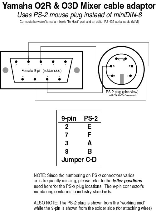
Yamaha 02R/03D
audio mixers and Fastrack interconnect adaptor cable
Connects between a COM port serial cable
on the Fastrack and the HOST port on the Yamaha mixer.
DB-9 Female at Fastrack COM port, PS-2 Type Male at mixer (alignment
stud removed)
RS-422 DB-9
Male |
Description |
PS-2 Type
Male |
|
2 |
RxA |
E |
|
3 |
TxB |
A |
|
7 |
TxA |
F |
|
8 |
RxB |
B |
|
Shield |
Chassis Ground |
Shield |
|
|
Jumper C to D |
(Click HERE
for diagram view of this interconnect cable;  205Kb,
01/16/03)
Back to TOP
Evertz HD9625DSK
Tech Note ( 205Kb,
01/16/03)
Back to TOP
Evertz HD9625DSK
Tech Note ( 73Kb, 3 pages) 73Kb, 3 pages)
HD9625DSK GPI connector
DB-15
Male |
Description |
|
10 |
+3.3v (jumper to 15) |
|
15 |
Vext (jumper to 10) |
|
8 |
GPI A (1) |
|
14 |
GPI B (2) |
|
5 |
GPI C (3) |
|
9 |
GPI D (4) |
|
12 |
GPI E (5) |
|
7 |
GPI F (6) |
|
13 |
GPI G (7) |
|
11 |
GPI H (8) |
|
1 |
Ground |
Fastrack GPI connector (DB-25 male)
|
GPI# |
Collector
Pin |
Emitter
Pin |
|
1 (A) |
1 |
14 |
|
2 (B) |
2 |
15 |
|
3 (C) |
3 |
16 |
|
4 (D) |
4 |
17 |
|
5 (E) |
5 |
18 |
|
6 (F) |
6 |
19 |
|
7 (G) |
7 |
20 |
|
8 (H) |
8 |
21 |
|
+5v |
Pin 24 |
Note: All Emitters should be tied together to Pin 1 of DB15 (ground)
on HD9625DSK
Example: For GPI #1 on Fastrack connected to
GPI A on the HD9625DSK:
|
Evertz DB15 Male |
SIGNAL |
Fastrack DP25 Male |
|
10 to 15 |
Jumpered |
n/a |
|
1 |
Ground / Low |
14 |
|
8 |
GPI A / High |
1 |
Back to TOP
|
|